|
|
|
Usuarios conectados
Actualmente hay 5905 visitantes online. |
|
Productos
|
|
Información
|
|
Destacado
|
|
|
 |
|
- SERVICING NOTE
- GENERAL
- DISASSEMBLY
- Front Panel Block
- CD Mechanism Deck
- BU Bracket Assembly
- Disc Table
- TEST MODE
- ELECTRICAL BLOCK ADJUSTMENTS
- DIAGRAMS
- Circuit Boards Location
- Schematic Diagram — BD Section
- Printed Wiring Board — BD Section
- Schematic Diagram — Main Section
- Printed Wiring Board — Main Section
- IC Pin Function
- IC 401 System Control, Fluorescent Indicator Tube Drive (CXP82316 - 065Q)
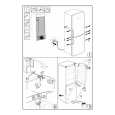
- EXPLODED VIEWS
- Case and Back Panel Section
- Front Panel Section
- CD Mechanism Section (CDM37 - 5BD19)
- Base Unit Section (BU - 5BD19)
- ELECTRICAL PARTS LIST
No hay comentarios de productos.
SECTION 5 ELECTRICAL BLOCK ADJUSTMENTS
Note : 1. CD Block is basically designed to operate without adjustment. Therefore, check each item in order given. 2. Use YEDS-18 disc (3-702-101-01) unless otherwise indicated. 3. Use an oscilloscope with more than 10M impedance. 4. Clean the object lens by an applicatior with neutral detergent when the signal level is low than specified value with the following checks. 5. Adjust the focus bias adjustment when optical block is replaced. Focus Bias Adjustment
oscilloscope (DC range) BD board TP(RF) TP(VC)
S Curve Check Note : Use the widely use remote commander with 20 keys for this check.
oscilloscope BD board TP(FEO) TP(VC)
Procedure : 1. Connect oscilloscope to test point TP (FEO). 2. Connect between test point TP (ADJ) on DISPLAY board to Ground with a lead wire. 3. Turn Power switch on to set the ADJ mode. 4. Put disc (YEDS-18) in and set to the stop mode. 5. Press the �15� button and actuate the focus serach. 6. Check the oscilloscope waveform (S-curve) is symmetrical between A and B. And confirm peak to peak level within 2.4 ± 0.7 Vp-p. S-curve waveform
Symmetry
Procedure : 1. Connect oscilloscope to test point TP (RF). (Ground terminal : VC) 2. Turn Power switch on. 3. Put disc (YEDS-18) in and playback. 4. Adjust RV101 so that the waveform is clear. (Clear RF signal waveform means that the shape ��� can be clearly distinguished at the center of the waveform.) 5. After adjustment, check the RF signal level. � RF signal VOLT/DIV : 200 mV TIME/DIV : 500 nS
A within 2.4 ± 0.7 Vp-p B
7. After check, remove the lead wire connected in step 2. Note : � Try to measure several times to make sure than the ratio of A : B or B :A is more than 10 :7. � Take sweep time as long as possible and light up the brightness to obtain best waveform. RF Level Check
level 1.3 ± 0.3 Vp-p BD board TP(RF) TP(VC) oscilloscope
Procedure : 1. Connect oscilloscope to test point TP (RF) on BD board. 2. Turn Power switch on. 3. Put disc (YEDS-18) in and playback. 4. Confirm that osilloscope waveform is clear and check RF signal level is correct or not. Note : Clear RF signal waveform means that the shape ��� can be clearly distinguished at the center of the waveform. RF signal waveform
VOLT/DIV : 200mV TIME/DIV : 500nS
level : 1.3 ± 0.3 Vp-p
�9�
|
|
|
> |
|