|
|
|
Usuarios conectados
Actualmente hay 5873 visitantes online. |
|
Productos
|
|
Información
|
|
Destacado
|
|
|
 |
|
|
No hay comentarios de productos.
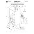
SECTION 1 SERVICING NOTES
TABLE OF CONTENTS 1. 2. 3. 4.
4-1. 4-2. 4-3. 4-4. CAUTION ON REPLACING FLASH MEMORY The BAD-BLOCK check* must be executed, when the flash memory in this set was replaced. The set will not operation normally, unless this check is finished. * The BAD-BLOCK check detects an area (bad-block) in the flash memory where data validity cannot be guaranteed, and saves this information in the TOC-AREA so that a bad-block is not used. BAD-BLOCK check Procedure: 1. Apply 1.5V from regulated power supply to the battery terminals. 2. Once the power is supplied, the check starts and then proceeds for approx. 20 seconds. (Be sure to keep applying the power during the check) 3. When the check completes, the result is shown as bellows. OK: Only the LCD back light LED (D503) turns on. NG: Red LED blinks or turns on or green LED turns on in the OPR LED (D504). 4. In case of OK, press the [STOP] button.
Note: � In case of NG, check system control IC (IC701), flash memory IC and the peripheral circuit. (Particularly, check carefully the soldering of the flash memory) � After finishing the BAD-BLOCK check, assemble the set, load the dry battery, and confirm if the set operates normally.
SERVICING NOTES ............................................... 2 GENERAL ................................................................... 3 DISASSEMBLY ......................................................... 4 DIAGRAMS
Block Diagram ................................................................ Printed Wiring Board ...................................................... Schematic Diagram ......................................................... IC Pin Function Description ........................................... 7 9 11 17
5. 6.
EXPLODED VIEW ................................................... 19 ELECTRICAL PARTS LIST ............................... 20
Notes on chip component replacement � Never reuse a disconnected chip component. � Notice that the minus side of a tantalum capacitor may be damaged by heat. Flexible Circuit Board Repairing � Keep the temperature of the soldering iron around 270 �C during repairing. � Do not touch the soldering iron on the same conductor of the circuit board. (within 3 times) � Be careful not to apply force on the conductor when soldering or unsoldering.
�2�
|
|
|
> |
|