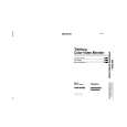
3-4. FOCUS ADJUSTMENT
1. Receive the monoscope signal. 2. Set the CONTR control to normal. 3. Adjust the FOCUS control of the FBT so that the focus at the center of CRT screen and around the CRT screen become optimum.
3-5-2. White Balance Adjustment
1. Receive the color bars signal. (Set the BURST switch of the test signal generator to OFF.) 2. Set the following controls on the front panel as follows: BRIGHT 8 Center click CONTR 8 Minimum BIAS (Front panel) 8 50 % GAIN (Front panel) 8 50 % 3. Adjust RV118 (SUB BRT) on the B board so that the blue stripe portion on the color bars signal is bright dimly.
Colorbar pattarn
FOCUS
FBT
Fig. 3-14
3-5. WHITE BALANCE ADJUSTMENT
3-5-1. Screen Voltage Adjustment
1. Receive the dot signal. 2. Connect a digital voltmeter to pin 5 (KG) of CRT socket. Adjust RV119 (G C/O) on the B board so that the voltage is 103 Vdc. 3. Connect a digital voltmeter to pin 9 (KB) of CRT socket. Adjust RV121 (B C/O) on the B board so that the voltage is 103 Vdc. 4. Adjust the SCREEN control of the FBT to the position where just before the flyback line disappears from the CRT screen.
WHITE Fig. 3-16
FBT
4. Receive the white signal. (Set the BURST switch of the test signal generator to OFF.) 5. Set the CONTR control to 90 degrees clockwise from the center position. 6. Using the luminance meter, adjust the luminance level of the CRT screen so that it is 3 Nit. (Screen is bright dimly.) 7. Adjust the white balance of the cut-off with RV119 (G C/O) and RV121 (B C/O) on the B board. 8. Set the luminance level of white signal to 100 IRE with test signal generator. 9. Adjust the white balance of the high-light with RV120 (G GAIN) and RV122 (B GAIN) on the B board. 10. Press the BLUE ONLY switch on the front panel. 11. Adjust the white balance of the high-light with RV124 (R GAIN/BL) and RV125 (G GAIN/BL) on the B board. 12. Using the luminance meter, adjust the luminance level on the CRT screen with test signal generator so that it is 8 Nit. Then confirm that the white balance is adjusted correctly.
YELLOW CYAN GREEN MAGENTA RED BLUE BLACK