|
|
|
Usuarios conectados
Actualmente hay 5909 visitantes online. |
|
Productos
|
|
Información
|
|
Destacado
|
|
|
 |
|
|
No hay comentarios de productos.
2.2 2.2.1
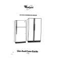
Receive Section RX Amps and SAW Filter The purpose of the first RX amp is to provide enough gain that the noise figure of the RX section is fixed to a value as low as possible. It must provide a good 50� match to both the RX bandpass filter and the SAW filter. This amplifier must also have good power handling capability due to the limited filtering which precedes it. The design employs a collector inductor to improve the output power capability of the transistor. This form of matching also ensures that the gain of this stage is not too wide band further improving its performance by allowing it to effectively reject signals which are far out of its passband. Directly following the first RX amp is the SAW filter. This filter is responsible for the bulk of the filtering in the receive section. It provides more than 40dB of image rejection and TX carrier suppression. The insertion loss of this filter is relatively high due to its SAW implementation. It has an insertion loss of less than 5dB, typically 4dB. An amplifier is required before this SAW filter to keep the noise figure low. If it were not present, the noise figure of the phone would increase by the 4dB Ioss associated with the SAW filter. The second RX amp provides a limited amount of gain. Its main function is to ensure that the mixer sees a good wideband match. Measuring the RX gain from the BFA connector to the output of this amplifier will produce results as shown in Figure 4 below.
925-928MHz Passband
0dB
10dB/div
875
902-905MHz Reject Band
97
Figure 4. RX Front end Response. ����������������������������� 2.2.2 RX Mixer The function of the mixer is to combine the incoming signal with a LO signal in order to convert the desired signal to the 10.7MHz IF frequency. The mixer used for this task is a dual gate FET (CF739R). The LO and RF signals are placed on the gates of the FET and the IF signal is coupled off of the drain. The FET provides conversion gain along with adequate power handling characteristics. Both the RF and LO ports are shorted to ground by rectangular microstrip inductors. These inductors provide a high impedance at both the RF and LO frequencies while presenting a very low impedance at the IF frequency. The mixer is followed by an emitter follower which converts the high impedance output of the mixer to a 330� output suitable for directly driving the IF ceramic filters. The gain for the pair (mixer and follower) is about 6dB (50� in, 330� out). RX VCO and LO Buffer The RX VCO is a Colpitt�s type oscillator operating at about 450MHz with a frequency selective network tuned to about 900MHz on the collector. The frequency of oscillation is controlled by a varactor diode in the tank circuit connected to the base of the transistor. This diode is connected to the loop voltage from the RX synthesizer. Rough tuning is achieved with a variable chip cap. This capacitor is used to center the tuning voltage to ensure reliable operation over a wide temperature range and also to compensate for variations in component values. The 450MHz LO for the PLL is coupled off of the emitter of the VCO transistor. This is lightly coupled to ensure that the VCO is not loaded by the PLL. The LO Buffer isolates the PLL from the VCO preventing the TX VCO from interfering with the RX VCO and vice versa. The 900MHz RX LO signal for the Mixer is coupled off the collector of the VCO transistor. 2.2.4 RX Synthesizer The PLL and prescaler for both the TX and RX sides are combined into one IC. The Synthesizer receives channel information from the audio board through the SPI buss. It also requires a stable 4.0MHz reference which is supplied from the MCU section.
2.2.3
� 17 �
|
|
|
> |
|