|
|
|
Usuarios conectados
Actualmente hay 6042 visitantes y
1 usuarios online. |
|
Productos
|
|
Información
|
|
Destacado
|
|
|
 |
|
|
No hay comentarios de productos.
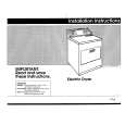
SECTION 3 DISASSEMBLY
Note: Follow the disassembly procedure in the numerical order given.
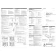
SECTION 4 ELECTRICAL ADJUSTMENT
IDLING CURRENT ADJUSTMENT
4 Bottom plate
3-1. SIDE PLATE,SUB 1/SUB 2 AND FILTER BOARD
1 Three screws (BTP3x8) 2 Three screws (BTP3x8)
� Perform adjustments in the HI-VOLTAGE mode. 1 Adjustment point Semi-fixed resistors VR101, VR201, VR301, VR401, VR501, VR502 of amplifier board 2 Precautions on adjustments 1. Set the RCA input terminal to open. 2. Apply a voltage of 14.4V between the +12V terminal, REMOTE terminal, and GND terminal. 3. Rotate the above semi-fixed resistors completely in the counterclockwise direction while observing the component side. 4. Check that the voltage at the adjustment point becomes 0 mV in step 2. 5. Fine adjustments may be required according to the characteristics of the MOS-FET used. � When adjusting the idling current Rotating the semi-fixed resistor in the clockwise direction: Increases the idling current Rotating the semi-fixed resistor in the counterclockwise direction: Decreases the idling current * Take note that rotating excessively in the clockwise direction will increase the idling current suddenly. 3 Approximate adjustment values Adjust as follows so that the following voltages become 1.2 to 0.3 mV around 0.7 mV . FL channel : Voltage between TP7 and TP6: Use VR101 of the amplifier board FR channel : Voltage between TP7 and TP5: Use VR201 of the amplifier board RL channel : Voltage between TP7 and TP4: Use VR301 of the amplifier board RR channel : Voltage between TP7 and TP3: Use VR401 of the amplifier board SUBWOOFER Channels : First, adjust so that the voltage between TP1 and TP2 becomes 1.2 to 0.3 mV around 0.7 mV using VR501 of the amplifier board. Next, adjust so that the voltage between TP1 and TP2 becomes 2.4 to 0.6 mV around 1.4 mV using VR502 of the amplifier board.� Connection :
6 Power board
3 Two screws (BTP3x8) !§ Filter board !� Screw (BTP3x8)
!ª Screw (BTP3x8) @º Sub 2 board @¡Sub 1 board @§ Fan motor block @¢ Screw (BTP3x8) @� TR board 0 Side plate (R)
5 Three screws
(BTP3x8)
7 Side plate (L)
6 Screw (BTP3x8)
!¢ Auto fuse (F901 to F904) !� Screw (M4) !£ Cover !¶ CNP710 (10P)
8 Three screws (BTP3x8) @£ CNP708 (2P) @� CNP803 (3P)
!� Screw (BTP3x12) 9 Screw (BTP3x8) !¡ Screw (M4)
3-2. AMPLIFIER/POWER BOARD AND LED BOARD
2 Four screws !¡ Six screws (P3x10) 3 Six screws (BVTP3x14)
(P4x40)
!£ Sub heat sink (Amplifier) 0 Screw (BTP3x8) 4 Two Retainers 5 Two screws (BVTP3x10)
Adjustment Location � AMPLIFIER BOARD � (Component side)
9 Four screws (P3x10) 8 Two screws
(P3x14) !� Three screws (P3x6)
!¢ Two insulating sheets (AMP) !� Two screws (P2x10) !§ LED board !¶ LED holder
7 Amplifier board
Digital voltmeter
TP7 TP1 (SUB WOOFER)
JW307
TP6 TP5 TP4 TP3 TP2 TP1 (FL-CH) (FR-CH) (RL-CH) (RR-CH) (SUB WOOFER) (SUB WOOFER)
JW230 TP7 TP5 TP6 VR201 VR101 VR301 VR401 VR501 TP4 TP3 TP1 VR502 TP2
1 Five screws (BTP3x12)
7
7
|
|
|
> |
|